
Page 9 - Abbott
P. 9
Patient and Hospital Electronics Systems
The CardioMEMS PA Sensor is implanted into a distal branch of the descending PA. Following implantation, patients are instructed
to take pressure readings from home as directed by their physician. The information transmitted to the database is immediately
available to clinicians for review. The information consists of pressure trend information and individual PA pressure waveforms.
The Patient and Hospital Electronics Systems have been designed to obtain information from the sensor. The functional components
of the hardware include an electronics unit and an antenna. The antenna simultaneously sends a Radio Frequency (RF) signal to
energize the sensor and measures the RF signal returned by the sensor. This returning signal is processed and stored in the
electronics unit.
There are two types of electronics systems: the Patient Electronics System and the Hospital Electronics System. The Patient
Electronics System is the primary means of monitoring. It is used at home by the patient to take regular measurements. The Hospital
Electronics System is used during sensor implant and when the patient needs measurements taken in a clinical setting.
The Hospital Electronics System should be mounted on a portable pole stand with wheels and stored in the Catheterization Lab area
or Heart Failure Clinic as needed by clinicians.
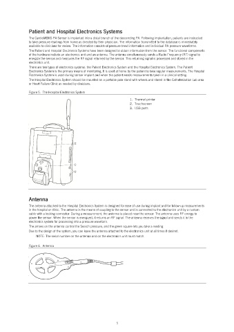
Figure 5. The Hospital Electronics System
1. Thermal printer
2. Touchscreen
3. USB ports
Antenna
The antenna attached to the Hospital Electronics System is designed for ease of use during implant and for follow-up measurements
in the hospital or clinic. The antenna is the means of coupling to the sensor and is connected to the electronics unit by a custom
cable with a locking connector. During a measurement, the antenna is placed near the sensor. The antenna uses RF energy to
power the sensor. When the sensor is energized, it returns an RF signal. The antenna receives the signal and sends it to the
electronics system for processing into a pressure waveform.
The arrows on the antenna control the Search pressure, and the green square lets you take a reading.
Due to the design of the system, you can leave the antenna attached to the electronics unit at all times if desired.
NOTE: The serial number on the antenna and on the electronics unit must match.
Figure 6. Antenna
5