
Page 7 - Abbott
P. 7
Sterilization
The Hospital Electronics System is provided non-sterile.
Components and Setup
Connect the System Cables
1. Align the keyed antenna at an approximately 30 degree angle and twist on the locking connector.
Figure 1. Connecting the antenna
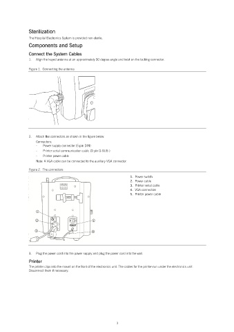
2. Attach the connectors as shown in the figure below.
Connectors:
- Power supply connector (5 pin DIN)
- Printer serial communication cable (9 pin D-SUB )
- Printer power cable
Note: A VGA cable can be connected to the auxiliary VGA connector.
Figure 2. The connectors
1. Power switch
2. Power cable
3. Printer serial cable
4. VGA connection
5. Printer power cable
3. Plug the power cord into the power supply and plug the power cord into the wall.
Printer
The printer clips into the mount on the front of the electronics unit. The cables for the printer run under the electronics unit.
Disconnect them if necessary.
3