
Page 67 - Abbott
P. 67
The system should not be modified. The user of this equipment is responsible for reading, understanding, and following the Warning
and Precaution statements presented within this manual.
Electromagnetic Interference and Electromagnetic Compatibility
This section provides a brief overview of Electromagnetic Interference and Electromagnetic Compatibility guidance associated with
the use of the CM3000.
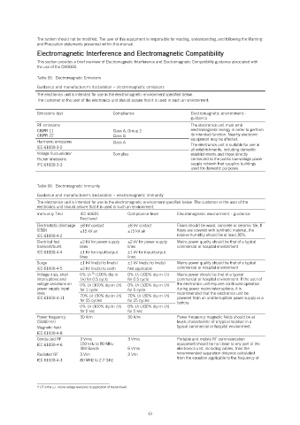
Table 15. Electromagnetic Emissions
Guidance and manufacturer’s declaration – electromagnetic emissions
The electronics unit is intended for use in the electromagnetic environment specified below.
The customer or the user of the electronics unit should assure that it is used in such an environment.
Emissions test Compliance Electromagnetic environment -
guidance
RF emissions The electronics unit must emit
CISPR 11 Class A, Group 2 electromagnetic energy in order to perform
CISPR 22 Class B its intended function. Nearby electronic
Harmonic emissions Class A equipment may be affected.
IEC 61000-3-2 The electronics unit is suitable for use in
all establishments, including domestic
Voltage fluctuations/ Complies establishments and those directly
Flicker emissions connected to the public low-voltage power
IEC 61000-3-3 supply network that supplies buildings
used for domestic purposes.
Table 16. Electromagnetic Immunity
Guidance and manufacturer’s declaration – electromagnetic immunity
The electronics unit is intended for use in the electromagnetic environment specified below. The customer or the user of the
electronics unit should assure that it is used in such an environment.
Immunity Test IEC 60601 Compliance level Electromagnetic environment - guidance
Test level
Electrostatic discharge ±8 kV contact ±8 kV contact Floors should be wood, concrete or ceramic tile. If
(ESD) ±15 kV air ±15 kV air floors are covered with synthetic material, the
IEC 61000-4-2 relative humidity should be at least 30%.
Electrical fast ±2 kV for power supply ±2 kV for power supply Mains power quality should be that of a typical
transient/burst lines lines commercial or hospital environment
IEC 61000-4-4 ±1 kV for input/output ±1 kV for input/output
lines lines
Surge ±1 kV line(s) to line(s) ±1 kV line(s) to line(s) Mains power quality should be that of a typical
IEC 61000-4-5 ±2 kV line(s) to earth Not applicable commercial or hospital environment
Voltage dips, short 0% UT (100% dip in 0% UT (100% dip in UT) Mains power should be that of a typical
15
interruptions and UT) for 0.5 cycle for 0.5 cycle commercial or hospital environment. If the user of
voltage variations on 0% UT (100% dip in UT) 0% UT (100% dip in UT) the electronics unit requires continued operation
power supply input for 1 cycle for 1 cycle during power mains interruptions, it is
lines recommended that the electronics unit be
IEC 61000-4-11 70% UT (30% dip in UT) 70% UT (30% dip in UT) powered from an uninterruptible power supply or a
for 25 cycles for 25 cycles battery.
0% UT (100% dip in UT) 0% UT (100% dip in UT)
for 5 sec for 5 sec
Power frequency 30 A/m 30 A/m Power frequency magnetic fields should be at
(50/60 Hz) levels characteristic of a typical location in a
Magnetic field typical commercial or hospital environment.
IEC 61000-4-8
Conducted RF 3 Vrms 3 Vrms Portable and mobile RF communication
IEC 61000-4-6 150 kHz to 80 MHz equipment should be no closer to any part of the
ISM Bands 6 Vrms electronics unit, including cables, than the
Radiated RF 3 V/m 3 V/m recommended separation distance calculated
IEC 61000-4-3 80 MHz to 2.7 GHz from the equation applicable to the frequency of
15 UT is the a.c. mains voltage level prior to application of the test level.
63